
Motion Control Solutions for an Agtech Prototype
Building a better wheelbarrow
If you need a 700 horsepower GPS-guided combine to harvest 7,200 bushels of corn per hour, John Deere has had you covered since 1996. But what if you need a 0.7 horsepower remote-controlled wheelbarrow to haul 7.2 bushels of corn to the other side of your family's organic produce farm?
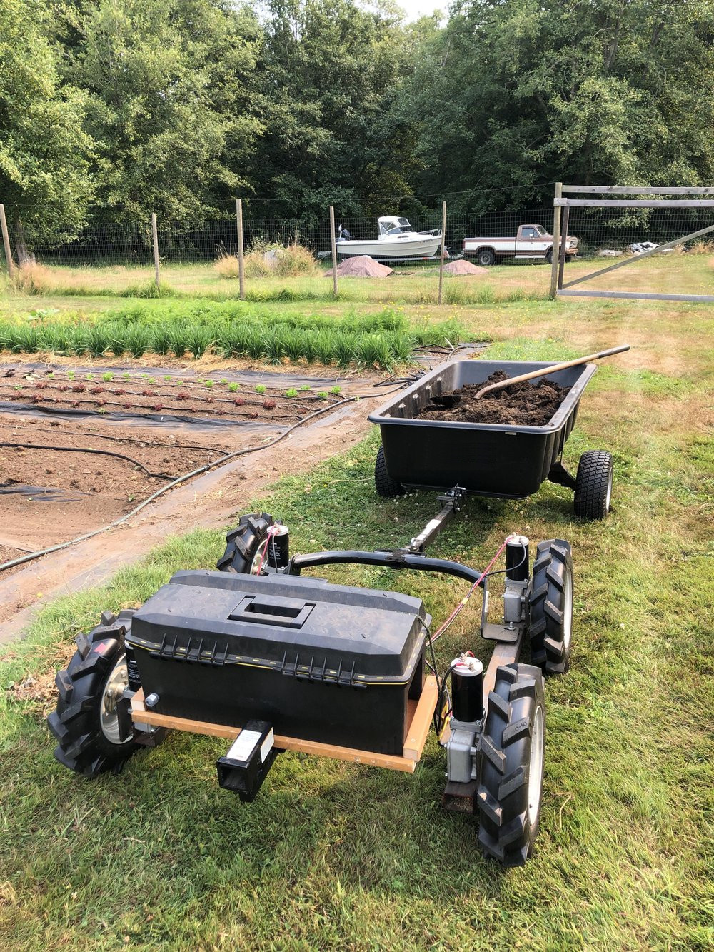
That's the problem All-Purpose Electric set out to solve, and it's the reason they reached out to us for help developing a remote-control wheelbarrow called the TerraTug.
Our team implemented arcade-style joystick mixing and skid-steer kinematics for the TerraTug prototype using the quirky microbasic scripting language built into their chosen motor controller.
This was a fun, quick project that might be interesting for anyone who is curious about skid-steer kinematics, joystick mixing, or the Roboteq microbasic scripting language.
If you're building robots in agriculture or any other field (pun intended), send us a message!
We'd love to learn about your project and explore ways to help.
↓ Jump to the video!
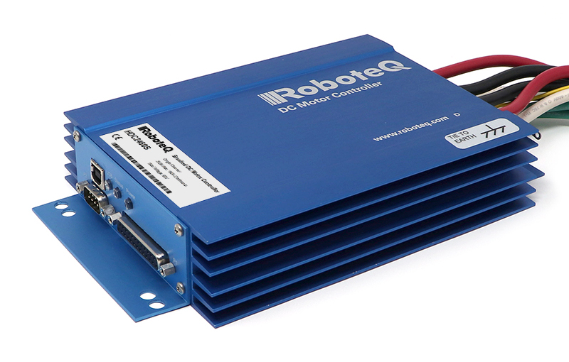
The Roboteq HDC2460S
The TerraTug prototype uses a Roboteq HDC2460 dual channel DC motor controller. We've used Roboteq motor controllers in the past for borehole and pipe inspection robots, and we've found these motor controllers to be robust and reliable. Once you've got the software and configuration sorted out, the Roboteq controllers are great. Sadly, the software for configuring and programming the controllers has been a perennial source of frustration.
The primary interface for working with these devices is a Windows-only GUI called RoboRun. Using RoboRun, you can change PID coefficients, configure limit switches, send commands to your motors, and upload scripts to the controller to reprogram its default control loop. In the past, we've used the serial protocol to send commands directly to the motor controllers. At that time, the protocol was poorly documented, slow, and difficult to work with, but since then they have created an officially supported C++ library and ROS bindings that should make it a lot easier to connect a computer and communicate directly with the controllers.
For simple remote-control projects like TerraTug, the built-in microbasic scripting language is the easiest way to go, so long as you don't mind learning a few quirks and working around the occasional bug. We once spent an entire night debugging a motor controller fault that turned out to be a broken division operator in the scripting language—instead of dividing by our gear ratio, we had to multiply by its reciprocal to avoid the broken instruction. We contacted Roboteq's engineers, and they rolled out a firmware update within a few days.
The Microbasic Scripting Language
The Roboteq scripting language—microbasic—is mostly straightforward, but expect to consult the reference manual regularly as you work. Here are a few quirks that are worth knowing about:
- Presumably to avoid floating-point math, several of the built-in math functions require scaled inputs and produce scaled outputs.
For example,
Atan()accepts its argument scaled by a factor of 1000 and returns its result scaled by a factor of 10, soAtan(1000)will evaluate to450. - Trig functions operate in (scaled) degrees, not radians.
- The comparison operator is single-equals "
If a=b Then", not double-equals "if(a == b)" like we're used to with C-like syntax. - The not-equals comparison operator is "<>", not "!=" like C,C++,Python, etc, or "~=" like MatLab.
- All variables are global, their scope extends throughout the entire program.
Joystick Input Mapping
Our first step was to map the joystick coordinates as seen by the motor controller. We wrote a simple script to get the x and y-axis joystick values and print them to the serial console built into the RoboRun GUI.
main:
    ' Get the remote control input for channel 1.
    joy_x = GetValue(_PIC, 1)
    ' Get the remote control input for channel 2.
    joy_y = GetValue(_PIC, 2)

    Print(joy_x)
    Print(", ")
    Print(joy_y)
    Print("\n")

    Wait(100)
    GoTo main
This script gave us the following mapping from joystick position to (joy_x, joy_y) coordinates:
- Joystick ↖ produces (-1000, -1000)
- Joystick ↗ produces (+1000, -1000)
- Joystick ↘ produces (+1000, +1000)
- Joystick ↙ produces (-1000, +1000)
Joystick forward produces -1000 and joystick backward produces +1000. Let's flip the y-axis to better match our intuition:
    ' Flip the joystick y axis so that joystick forward
    ' maps to +1000 and joystick backward maps to -1000.
    joy_y = -1 * joy_y
Now our x-axis points to the robot's right, and our y-axis points forward.
- Joystick ↖ produces (-1000, +1000)
- Joystick ↗ produces (+1000, +1000)
- Joystick ↘ produces (+1000, -1000)
- Joystick ↙ produces (-1000, -1000)
Joystick Deadzone
Even expensive joysticks don't always return to center perfectly every time.
When they don't, they can accidentally transmit a small input like +6 even when they joystick is at rest.
This can make the robot feel twitchy, since the motors will activate when the robot should be at rest. An easy way to avoid this is to add a deadzone to the joystick inputs. If the input is close enough to zero, we consider it zero. Here, we chose to ignore any inputs with a y-axis value between -10 and 10. This prevents the robot from twitching, and it ignores pure left-right joystick inputs that are impossible for this robot to obey.
#define DEADZONE_Y 10

    ' If the joystick inputs are small, send zeros to the motors.
    If Abs(joy_y) < DEADZONE_Y Then
        left_motor = 0
        right_motor = 0
        GoTo send_commands
    End If
Skid-Steer Kinematics
Now that we understand the joystick inputs, let's use the [joy_x, joy_y] input vector to command the robot to move.
We'll use the magnitude of the joystick vector to set the robot's velocity, and we'll use the angle of the joystick vector to set the curvature of the robot's path.
Using joystick magnitude to control speed
Let's start by calculating the magnitude of the joystick vector.
We can use the built-in microbasic Sqrt() instruction. Since we don't need the additional precision, we can go ahead and divide out the extra factor of 1000 that the built-in Sqrt() function adds to its output.
joy_mag = Sqrt(joy_x*joy_x + joy_y*joy_y) / 1000
This calculation produces 1412 for diagonal inputs and only 1000 for horizontal and vertical inputs, meaning the robot will drive faster for diagonal joystick inputs like ↖ and slower
for vertical inputs like ↑.
This causes the robot to leap forward unexpectedly when the user commands it to turn, so let's clamp the magnitude to the range [-1000, 1000]. This will make sure the robot achieves its maximum speed when the user commands full-forward or full-reverse.
    If joy_mag > 1000 Then
        joy_mag = 1000
    ElseIf joy_mag < -1000 Then
        joy_mag = -1000
    End If
Now we can set the robot's velocity proportional to the magnitude of the joystick input. If the joystick is pushed forward, the velocity is positive (forward). If the joystick is pulled backward, the robot's velocity is negative (reverse).
    If joy_y >= 0 Then
        velocity = joy_mag
    Else
        velocity = -1 * joy_mag
    End If
In either case, the robot moves faster as the joystick is pushed farther from its rest position.
Using joystick angle to control curvature
We want to use the angle of the joystick to command the curvature of the robot's path.
Many languages offer a function like std::atan2() or numpy.arctan2() that will calculate this angle directly, but microbasic does not have a built-in equivalent.
Fortunately, microbasic does support Atan(), so we can implement Atan2() ourselves in a subroutine.
Remember that all variables in microbasic have global scope, so let's push our arguments into variables called atan2_x and atan2_y. Then we can jump to the atan2 label, compute the value of atan2(atan2_y, atan2_x), and return the result in a variable called atan2_result.
atan2:
    If atan2_x > 0 Then
        atan2_result = Atan(1000*atan2_y/atan2_x)

    ElseIf (atan2_x < 0) And (atan2_y >= 0) Then
        atan2_result = Atan(1000*atan2_y/atan2_x) + 1800

    ElseIf (atan2_x < 0) and (atan2_y < 0) Then
        atan2_result = Atan(1000*atan2_y/atan2_x) - 1800

    ElseIf (atan2_x = 0) And (atan2_y > 0) Then
        atan2_result = 900

    ElseIf (atan2_x = 0) And (atan2_y < 0) Then
        atan2_result = -900

    ElseIf (atan2_x = 0) And (atan2_y = 0) Then
        atan2_result = 0
    End If
    return
Here is the calling code for our atan2 subroutine. We set the inputs, jump to the atan2 label, and retrieve the solution.
    ' Compute the angle of the joystick relative to the +x axis.
    atan2_x = joy_x
    atan2_y = joy_y
    GoSub atan2
    joy_arg = atan2_result
The result joy_arg now represents the angle between the joystick and the +X joystick axis.
We can now shift the joy_arg angle by 90 degrees and rescale to the range [-1000, 1000] to set the curvature for the robot's path.
    If joy_arg >= 0 Then
        curvature = ((joy_arg-900) * 1000) / 900
    Else
        curvature = -1 * ((joy_arg+900) * 1000) / 900
    End If
The curvature variable now represents the curvature of the robot's path scaled by a factor of 1000.
A hard-left turn will have a curvature of -1000, and a hard-right turn will have a curvature of +1000.
Driving straight forward or backward will produce a curvature value of 0.
Compute the left and right motor speeds.
At this point, we've calculated the velocity and curvature of the arc that the robot should traverse, but we still need to compute the velocities for the left and right motors. Let's define three points on the robot—the left wheel, center of the robot, and right wheel—and assign them velocities , , and .

All three points take the same amount of time to traverse their arc segment.
We can solve for in terms of the robot's velocity and the radius of the arc.
The left-side turning radius is equal to the arc radius minus half of the width of the robot .
And the arc radius is the inverse of the curvature .
The derivation for the right side velocity is similar, but the arc radius is rather than .
In code, the left and right motor velocities are calculated by these two lines:
    left_motor  = velocity * (1 - ROBOT_HALF_WIDTH * curvature)
    right_motor = velocity * (1 + ROBOT_HALF_WIDTH * curvature)
Send the commands to the motors.
Finally, we are ready to send velocity commands to the motors on the left and right side of the robot.
First, we clamp the left and right motor velocities to the range [-1000, 1000].
This is a cheap way to avoid a hardware fault if we send a command outside of the valid range.
Before we send the motor commands to the left and right drive motors, we need to reverse the command sent to the right side. The TerraTug prototype rover has mirrored drives on the left and right sides, so this makes sure the right side motors spin the correct direction.
Normally we would expect to multiply by the gearbox ratios and wheel circumferences to convert motor velocities to ground speed. Here we were able to cheat a little by having the user set his preferred maximum speed in the configuration GUI. Since this robot will never be computer controlled, it wasn't necessary to add these extra computations, and since we wanted our client to understand the code, we decided to simplify by leaving these calculations out.
send_commands:
    ' Clamp right_motor to [-1000, 1000].
    If right_motor > 1000 Then
        right_motor = 1000
    ElseIf right_motor < -1000 Then
        right_motor = -1000
    End If

    ' Clamp left_motor to [-1000, 1000].
    If left_motor > 1000 Then
        left_motor = 1000
    ElseIf left_motor < -1000 Then
        left_motor = -1000
    End If

    ' Flip the direction of the right motor so that
    ' +1000 drives the right side of the bot forward.
    right_motor = -1 * right_motor

    ' Send the commands to the motors.
    SetCommand(_GO, 1, left_motor)  ' Apply the command
    SetCommand(_GO, 2, right_motor) ' Apply the command

    Wait(100)
    GoTo main
Finally, we can send the velocity commands to the left- and right-side motors, delay for 100 milliseconds, and return to the start of the main control loop.
Testing in the Field
After implementing the control script and uploading it to the robot, we hitched TerraTug to a wheelbarrow and loaded it down with a few hundred pounds of plant litter. TerraTug hauled the towering wheelbarrow from the field to the compost heap, across the entire length of our client's farm, reducing three or four trips with a manual wheelbarrow to a single fun trip.
This quick project was a lot of fun, and it demonstrates the promising future of small-scale agricultural robotics. The TerraTug prototype is now helping our client's aging parents continue to work around their family farm, and our client is using lessons learned from TerraTug to develop a second, more refined prototype.

Roger Kubalek
"Rubicon understood my problem quickly and developed a fast, practical controls solution that worked! I appreciated their ability to communicate effectively and their attention to detail with all of the supporting documentation for the project. I look forward to working with them in the future."